The donor used for the demonstrator was a year 2000 MK2 1.8. Being a base model, the advantage with respect to the build, was that it did not have ABS, air con, central locking etc. making the stripping and fitting of the donor parts a little easier.
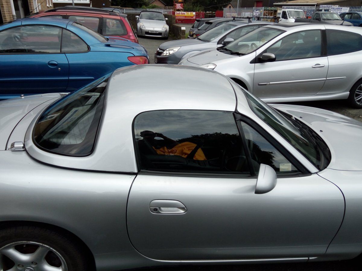
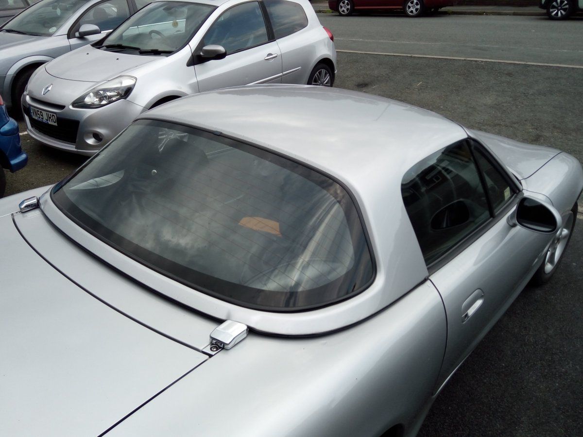
Several months previous to taking on the Replicar project, I had bought the MX-5 to use as a daily driver. It had only one owner from new, with a full comprehensive service history and new MOT. It also had a private plate and hard top (so was more expensive than the usual MOT failure type donor typically used. However, I recouped 2/3rds of its cost when it came to selling the parts not required - the hard-top fetching over £400 alone!)
Although the mechanicals were all in excellent condition and had proved themselves reliable over the preceding months, the body was beginning to suffer from the usual rot in the rear sills and front chassis legs - which is the reason I decided to use it as the donor.
SEPTEMBER 2017:-
Prior to starting the strip-down, all the body mounting nuts and bolts underneath the car were given a liberal dose of penetrating oil - as not only are they very tight but also very rusty from the years of being exposed to the elements. This would hopefully give the oil time to work whilst the strip-down takes place.
If you are intending to fully strip the rear hub assemblies to replace the wheel bearings etc, it is considered sensible practice to undo the extremely tight rear hub nuts at this stage - so as to take advantage of having the full weight of the car and handbrake to assist you.
However, having driven the car for several months, I knew there was absolutely nothing wrong with the bearings and therefore, in this case, there was no need to carry out this particular procedure.
To enable as much room and access as possible for the strip-down, the soft top roof and seats were removed first. Care had to be taken when removing all the trim and fastenings for the roof assembly, as many are hidden from view around the rear bulkhead and will prevent the roof being lifted away if missed.
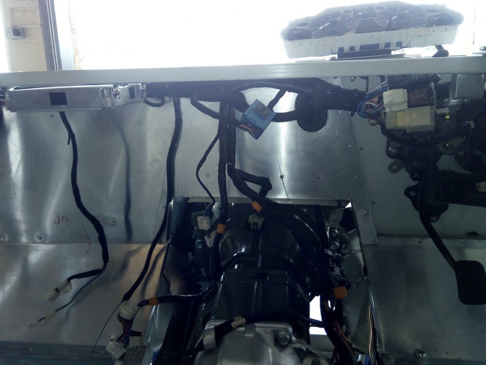
The fuel tank access panels were then removed, along with the boot lid, rear lights and bumper etc. to expose the rear of the wiring loom. Any electrical connectors were labelled clearly first before disconnecting (including any that are redundant) so as to aid identity when it comes to later re-installing the loom in the Replicar. The loom was then teased back through from the rear of the car into the cockpit area keeping as many connectors as possible still connected.
The centre console, carpet, doors and parts of the dash were then removed to further expose the wiring loom and allow access to it - especially that under the dash. Attention was then turned to the engine bay wiring, which again, was fully labelled before being disconnected and pulled carefully back through the bulkhead into the cockpit. Once freed from the dash panel, steering column etc. the entire loom could then be lifted from the vehicle and safely stored away in its own box.
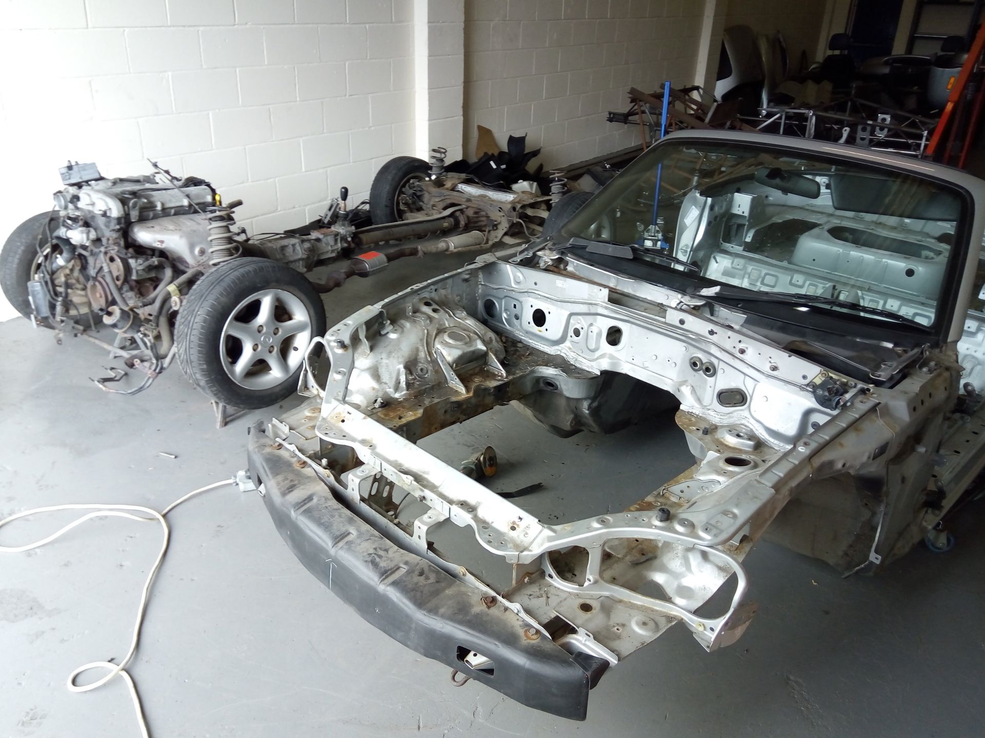
Any remaining interior dash assemblies were removed along with the steering column and pedal box etc. so as to leave the interior completely stripped. The front bumper, lights, bonnet, front wings, radiator airbox, rear silencer and exhaust mount rubbers etc. were then removed so that the shell was ready to be parted from the power plant frame underneath. It was important to remember to remove the VIN plate and cut out the VIN stamped in the bulkhead itself. This was so as to remove the ID of the vehicle to enable the body to be simply disposed of as scrap metal and not declared as a scrapped vehicle (which would otherwise lead to complications when using the donor vehicle's details at the time of registration.)
The body mounting bolts and nuts, having now had a good long soak in the penetrating oil applied at the outset, were then cracked off using a breaker bar and deep six-sided sockets to help prevent them rounding off. The centre nut on each coilover top mount were also undone an initial turn or so before 10" long temporary struts made from steel tube were jammed in on each corner between the lower wishbone and subframe. These were there to take the weight of the engine/transmission/powertrain assembly and prevent it from collapsing to the floor when the body was to be lifted from it. The mounting bolts and coilover nuts were then fully undone and removed so that the body was free to be lifted.
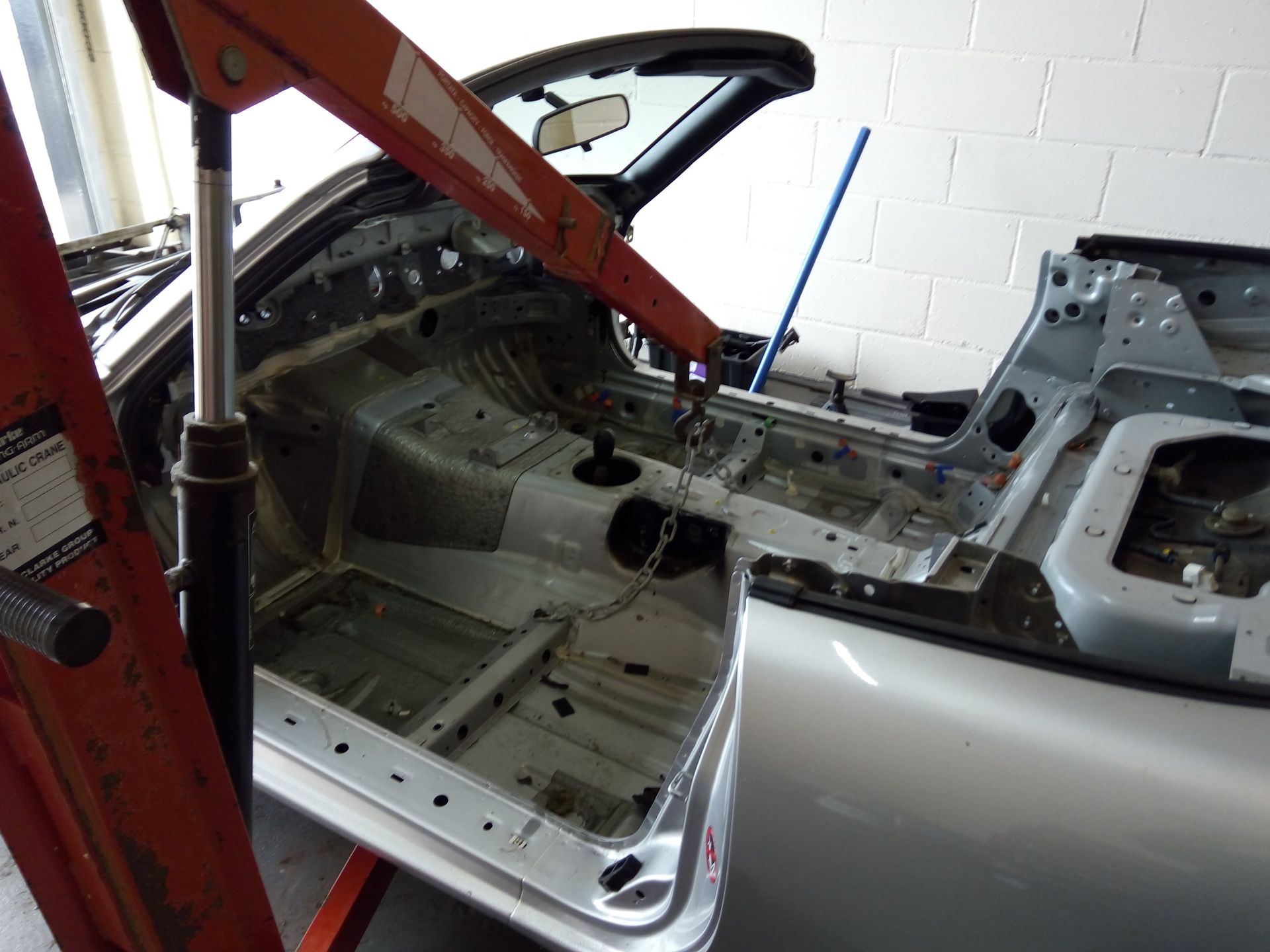
An engine hoist was then manoeuvred into position from the side so that its hook hung above the transmission tunnel and a lifting chain attached across the transmission tunnel as described in the build guide.
With the addition of extra manpower to help balance and guide the body, the crane was then used to lift it up and away from the underlying power plant assembly. A local scrap metal merchant then collected and disposed of the body - freeing up valuable workspace in the shop.
OCTOBER 2017:-
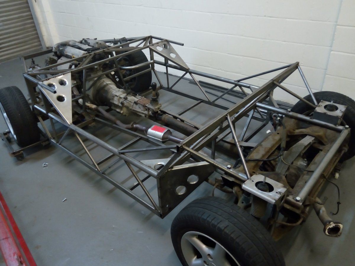
Meanwhile, the fabricator had been busy tacking the chassis together in its jig. Now that the power plant frame was free from the body, we decided it would be a good idea to trial fit the chassis to it - just in case it needed any tweaking before being clamped back in the jig and fully welded together. I am pleased to report no tweaking was necessary - a testament to the skills of the fabricator and accuracy of the jig!
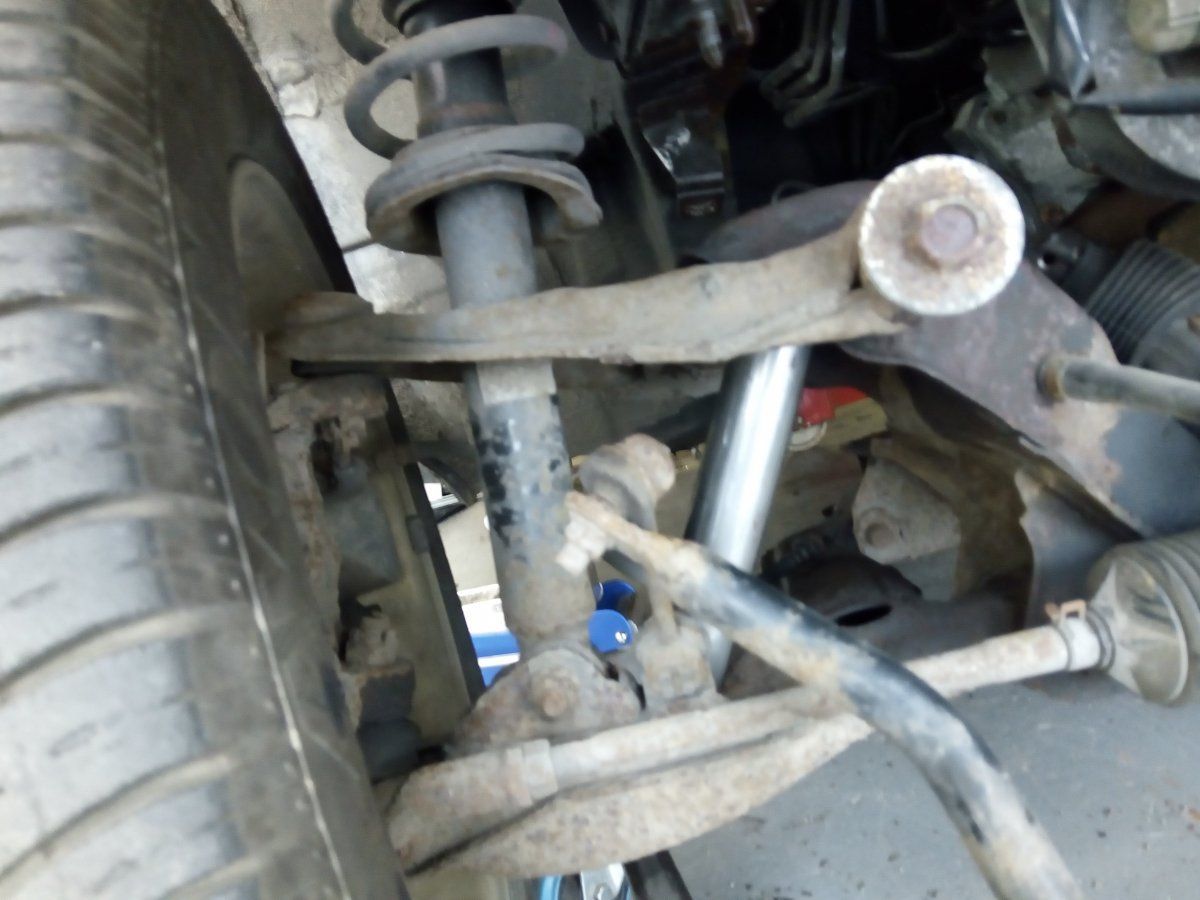
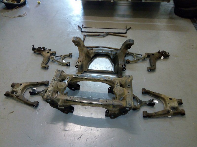
The stripping and reconditioning of the subframes and wishbones etc. could now begin.
Removing the wishbone pivot bolts proved 'challenging' to say the least - especially the rear outer lower wishbone (a common problem due to corrosion). However, patience is the order of the day and using a combination of penetrating oil, heat, impact gun and long breaker bar, the bolts finally yielded and with further working back and forth, eventually loosened enough to be removed.
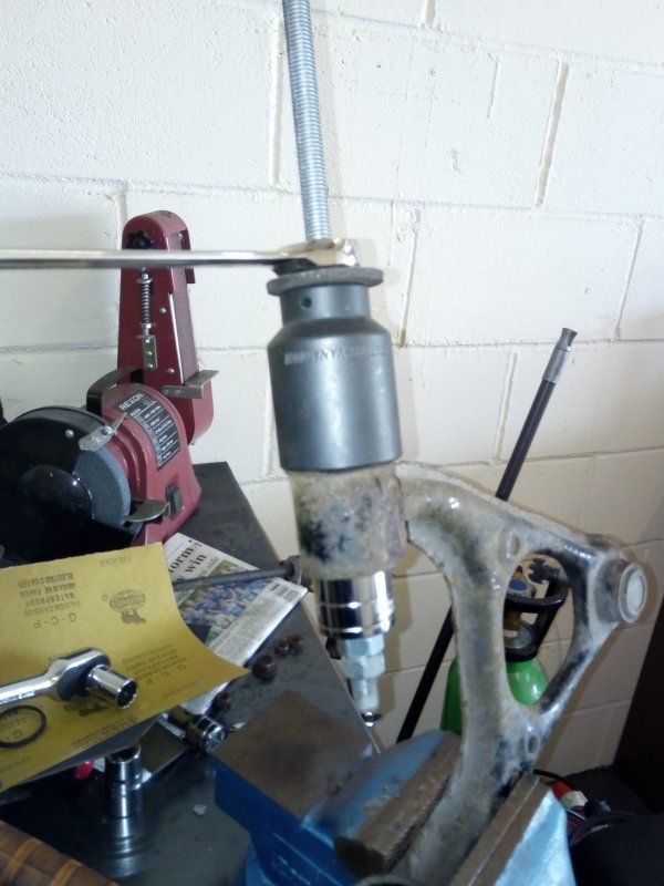
I decided that as some of the rubber bushes were showing signs of wear and having experienced the occasional creak or knock from the suspension whilst driving the donor, they would all be replaced with polyurethane bushes. Having done a lot of research, I settled upon fitting Super Pro bushes which although among the most expensive, were only a little dearer than OEM rubber. They are extremely well engineered and an accurate fit - meaning they will work correctly. Using a threaded bar with appropriate sized sockets (one slightly larger than the wishbone eye and the other slightly smaller than the outside dia. of the bush) the rubber bushes were drawn from the wishbones - which proved a long, labourious job as there are twenty two of them!
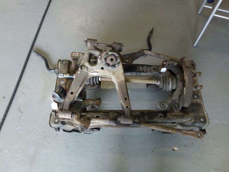
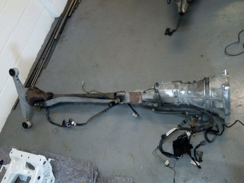
As I wasn't replacing the rear hub bearings, I disengaged the driveshafts from the diff and removed the driveshaft and hub carriers as complete assemblies (the brake calipers and discs having been removed previously).
I also elected to keep the diff bolted to the Power plant frame's aluminium spine as I could see little to be gained from seperating them (apart from making it a little easier to clean and repaint the diff etc, the bolts usually prove difficult to remove anyway) and ditto with the gearbox to spine mounting.
However, the engine and gearbox were seperated as I wanted to confirm that all the clutch components were indeed as new - as according to the service history, they had been replaced only a few months prior to my buying the donor. All was in order and it was also good to note that the catalytic convertor was a recent replacement too!
The GRP fabricator notified me that the body was ready to be popped from the moulds and would be available for collection in a day or two once the flashlines had been polished out. As the stripped subframes, wishbones and now fully welded chassis were ready for powder coating, they were loaded onto the trailer and despatched. The idea being that once done and collected, I could swing by the GRP shop on the way back and pick up the body - using the chassis to support the body on the trailer.
I have to say that I was really pleased with the quality of the work of both the body and powder coating - the wishbones etc. being unrecognisable from the rusty specimens they were previously.
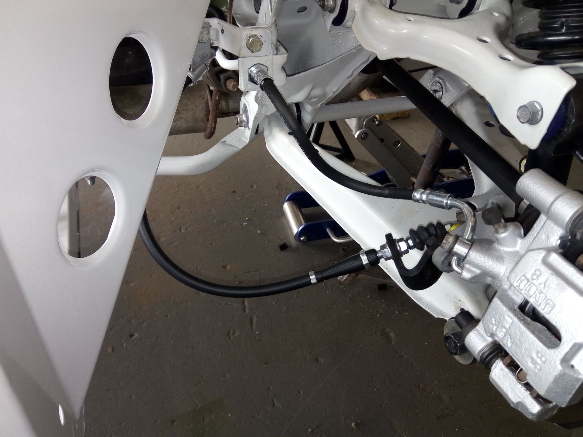
Wishing to have a break from the constant cleaning and reconditioning of all the donor parts, I thought I'd do a little work on the body. As the new 7" headlight assemblies had just been delivered (if a MK1 donor is used, then the headlights from it can be fitted) I decided I would cut out the holes to enable the headlight bowls to mounted in their recesses on the body.
There are a couple of methods that can be employed to create the large hole required. One is to simply use a large core drill (160mm dia.) but that does mean there is little margin for error - so the centre has to be very accurately marked to ensure the headlamp bowl is mounted centrally (it is very easy to remove material - but very difficult to put it back!)
The other is the one I used - which, although is more labour intensive, means that any slight error in the initial marking out can be easily remedied during the drilling out process.
Firstly, the area was masked off and using the headlight's rubber mounting gasket as a template, the outline for the bowl marked out. The circumference of the hole was then chain-drilled using a 3mm drill before moving on to a step drill to remove most of the material around the circumference.
A hacksaw blade could then cut through the small 'bridges' between each of the holes created by the step drill. The rough edges of the large hole left were then smoothed back carefully with a powerfile until the final correct diameter hole was attained.
The headlamp fixing holes were then drilled and the whole method repeated for the other side. The headlamps were then temporarily placed in position just to give the car its 'face' before being removed and packed away safely until such time as required to be fitted permanently.
NOVEMBER 2017:-
First job was to fit the polybushes to the wishbones (a much easier job than the removal of the original rubber ones!) and replace the front lower ball joints with new. The upper ball joints only needed repacking with grease and fitting with new rubber dust covers.
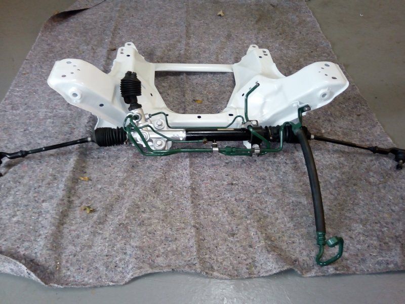
Assembly of the subframes could then begin. The rear subframe was assembled first before fitting it along with the freshly painted driveshafts to the diff using new rubber diff mounts. The diff, engine and gearbox had all previously been cleaned and freshly painted in an olive green to give them a 'period' look. The refurbed rear brake calipers and discs were then fitted along with new pads to complete the rear of the power plant frame.
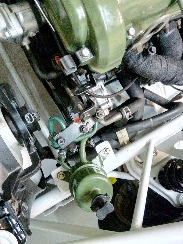
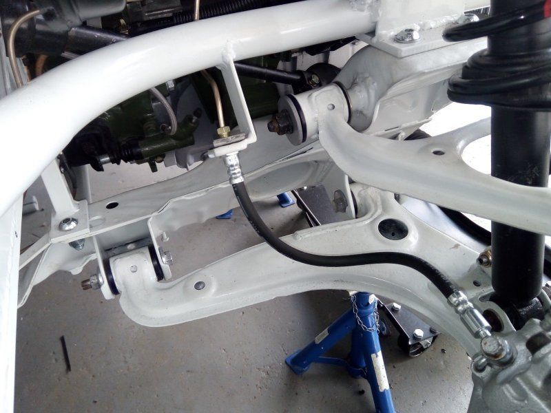
Attention could then be given to the front: Firstly, the refurbished steering rack was fitted to the front subframe. I was retaining the power steering capability due to the problem I have with my hands. To that end, I have added simple brackets to the chassis to mount the power steering fluid reservoir and these will also be included on all future customer chassis (the customer can always de-power the rack if they prefer).
The clutch and flywheel assembly was then refitted to the engine before it was re-united with the gearbox. Using the hoist to suspend the engine, the front subframe was offered up to it and secured using the engine mounts. The remainder of the front suspension components were added and the temporary struts once again fitted before lowering to the ground as a once again complete power plant frame.
Next on the agenda was to lay a large sheet of 1.5mm thick aluminium on the floor and sit the chassis on it to accrately mark the outlines of the floor panels and chassis members within them. The floor panels were then cut out using air shears and using the marked outlines of the chassis as a guide, 3mm pilot holes drilled at approx. 100mm centres along all fixing points.
Templates were then used to mark and cut out the transmission tunnel and front bulkhead panels from the same 1.5mm thick aluminium sheeting. The tunnel and panels were then folded into their final shape using a press brake folder. These were also marked and drilled using the same method as for the floor - then trial fitted to ensure correct alignment with the chassis and each other. However, they would not be permanently fitted until a little later in the build.
The chassis was then flipped over so that the chassis floor was uppermost and the floor panels clamped in place before drilling 5mm dia. holes through the pre-drilled pilot holes into the chassis members themselves. Having then removed the floor panels to vacuum away any swarf etc, a bead of light grey Tiger seal PU adhesive was applied to all floor chassis members before the panels were again positioned in place. Large head 4.8mm dia. x 12mm long blind rivets were then pushed through each of the pre-drilled holes to ensure correct alignment of the floor panels and chassis. A pneumatic rivet gun was finally used on the rivets to permanently fix the floor panels in place.
DECEMBER 2017:-
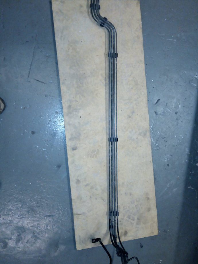
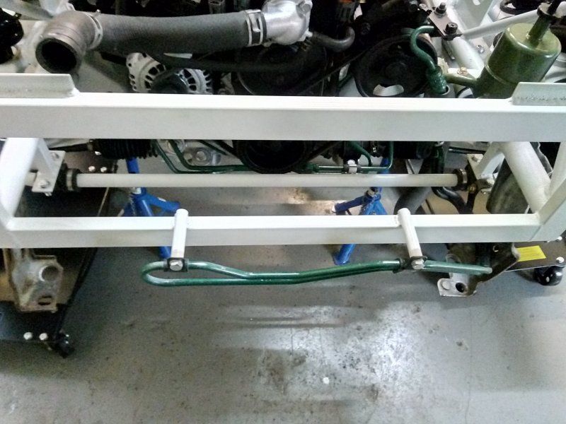
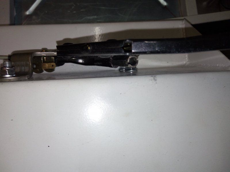
The last job to be done before mounting the chassis on the subframes was to consider how the front to rear brake and fuel lines would be run from in the transmission tunnel and what method of fixing to use. As there would be three lines (fuel supply and return plus a brake pipe) I didn't want to use individual P-clips for each line as it would look too cluttered and messy.
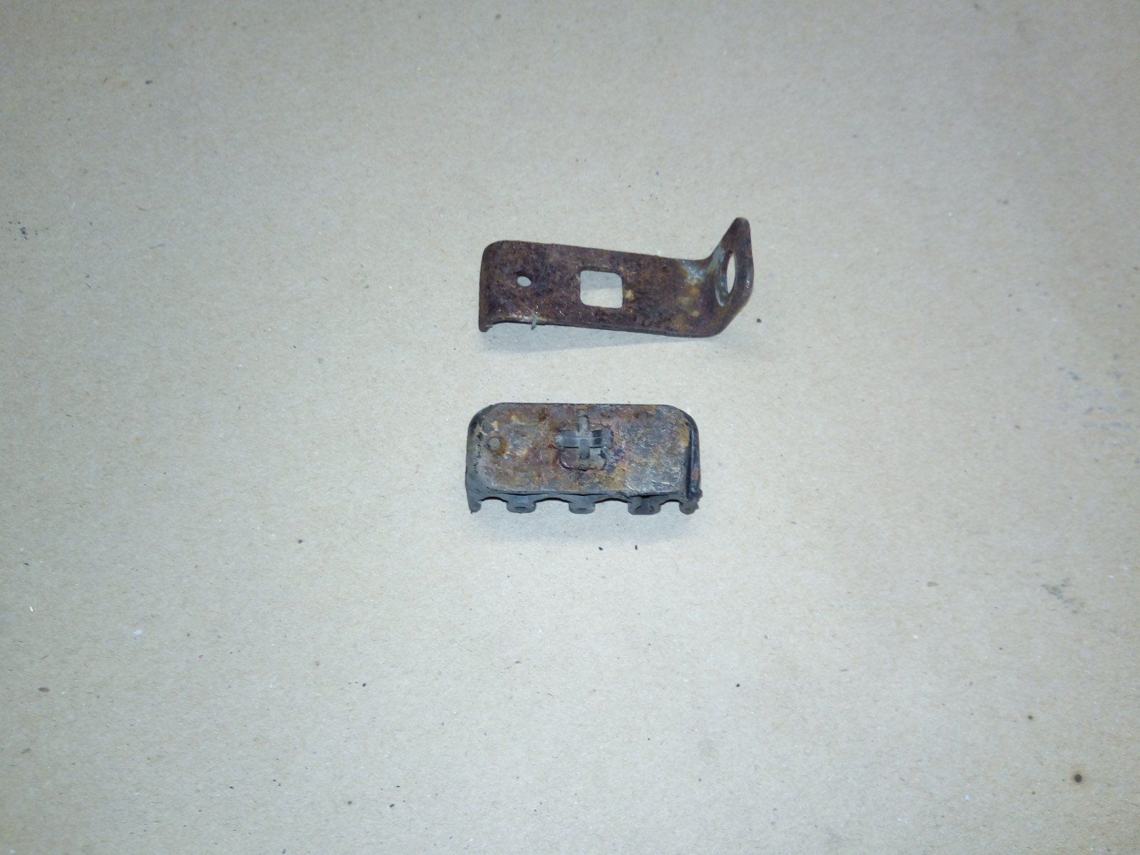
Rather than buy new (and expensive) 3-way clips, I realised that as I would be doing away with the carbon canister and associated pipework, I could modify and re-use the original 4-way retaining clips from the donor's fuel/brake lines. The original evap line from the fuel tank to carbon canister was covered in a plastic sheath which, conveniently, made it almost the same overall diameter as the 8mm fuel lines. Hence its redundant position on the outside of the clip could be used to move one of the fuel lines from the centre and its vacant position used for a mounting hole to affix the clip to the chassis.
To that end, the rusty mounting brackets were removed from the back of each clip and the clip backs smoothed flat on the belt sander. A 4mm fixing hole was then drilled through the clips in the position as described above. The clips were then offered up to the chassis in the appropriate positions along the inside of the transmission tunnel and using the pre-drilled holes as a guide to mark their centres, 3.5mm holes were drilled into the chassis itself. Stainless steel self tapping screws were then used to mount the clips.
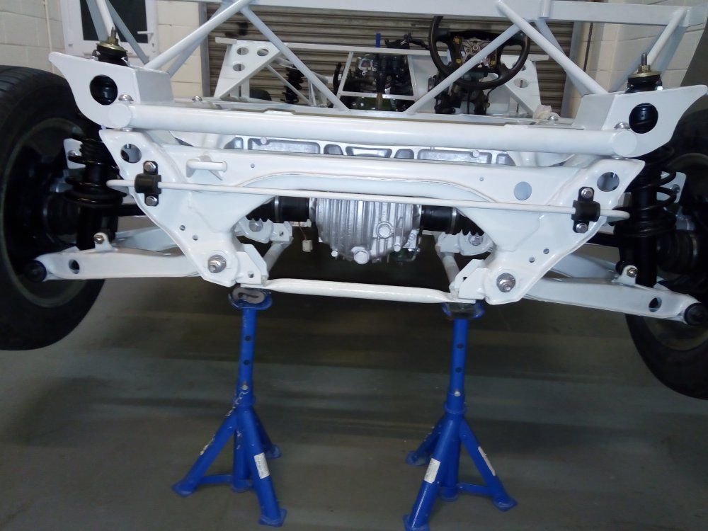
Finally, the chassis was mounted on top of the subframes using high tensile (10.9 grade) button head set screws and nyloc nuts.
The rear subframe brace was then shortened, re-profiled and the cut ends re-flattened. They were drilled so that the brace could be attached to the tabs on the bottom rear of the chassis (again, using high tensile fasteners) - thus further stiffening the rear subframe/chassis assembly.
Moving on, the driverside lower aluminium bulkhead/footwell panel was permanently fixed in place using the same method as the floor panels (except using standard 4mm rivets).
Next to be installed were the steering column and pedal box assembly. Initially, this all has to be loosely mounted before being gradually tightened - ensuring all the while that the lower column isn't binding where it passes through the bulkhead and rubber shroud. The rubber shroud is fixed in position by modifying and folding its original steel mounting ring so that it fits the profile of the bulkhead. Holes are then drilled through the bulkhead to align with the ring's mounting tabs and screws used to secure.
An aluminium sandwich plate was then made using an off-cut from the floor panels and a non-setting mastic sealing tape (such as used on caravan windows etc.) applied to the back of it to form a watertight seal between the clutch master cylinder and bulkhead. The brake servo and master cylinder was next to be installed and a square hole formed in the bulkhead to accept the accelerator cable's retaining clip.
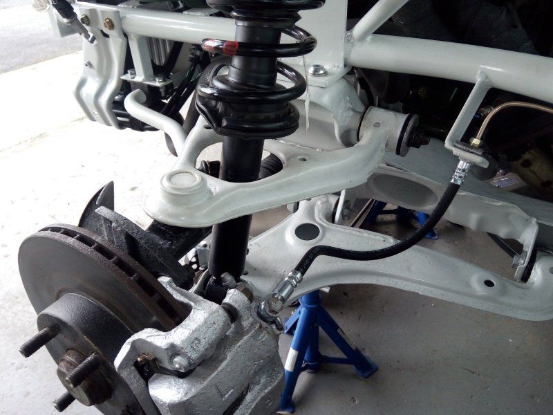
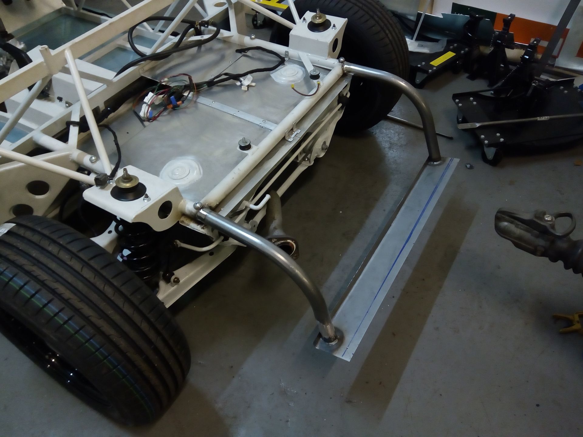
To complete the rolling chassis, the donor's freshly repainted coilovers were re-assembled using a coil spring compressor. These were installed along with the anti-roll bars and new drop links. Work could then begin on making and fitting new kunifer copper brake lines.
JANUARY 2018 :-
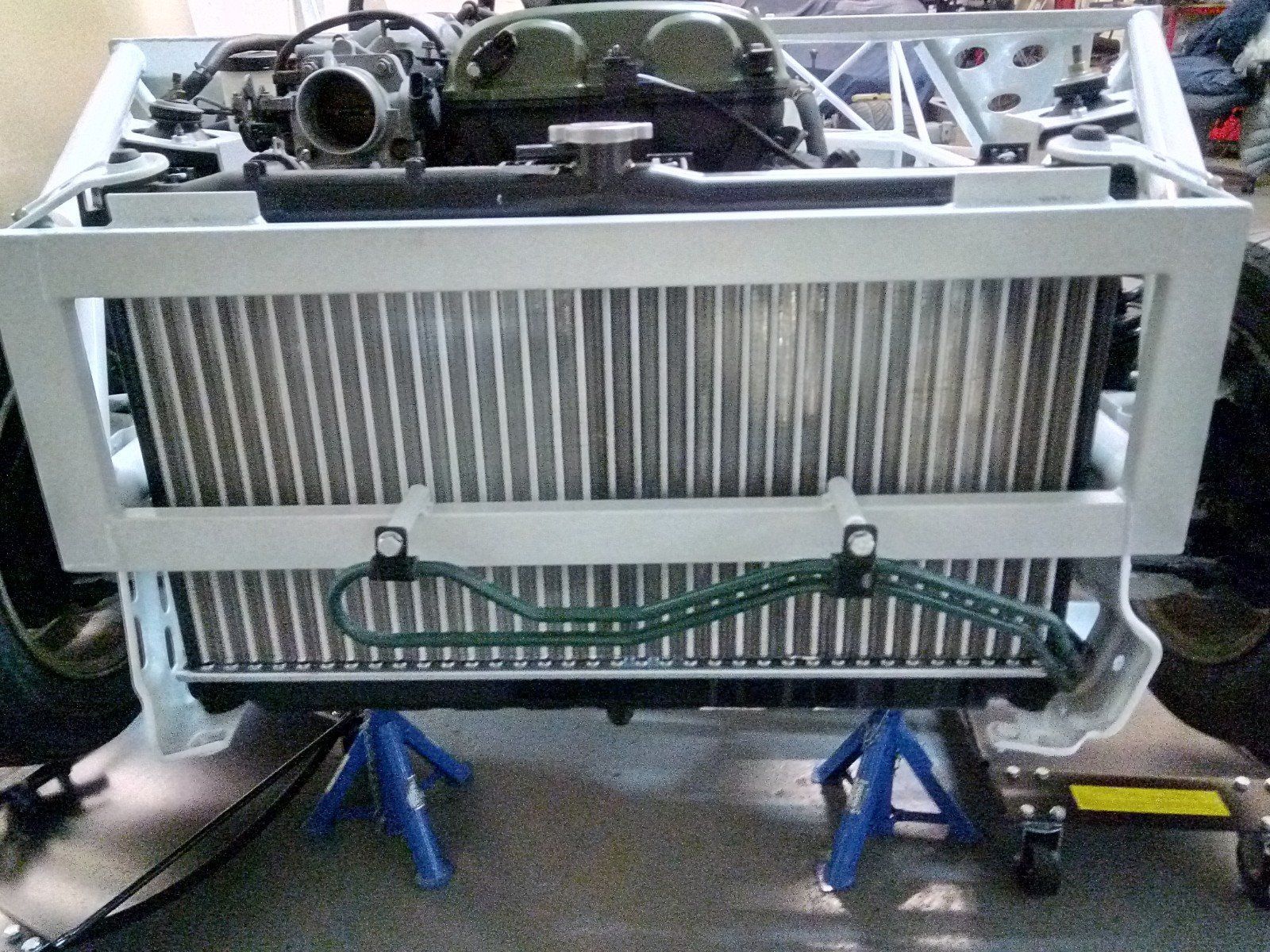
It was time to consider the mounting of the power steering pipework and to that end brackets were made out of mild steel tube before rivnuts were inserted in the ends. The brackets were then welded on to the front of the chassis so that the power steering cooling pipes would stand off the front of the radiator once fitted.
The PS reservoir was mounted in the engine bay using the tabs provided. In order for the reservoir to sit properly, it was necessary for a little shortening of the large hose from the reservoir to the PS pump and the lengthening of the narrower hose connecting the reservoir to the PS cooling pipe.
Moving on, the original radiator top and lower brackets retained from the donor were rubbed down and painted to match the grey powder coating of the chassis. The lower mounts were then bolted to the chassis and a new radiator lowered down on to them with the top brackets then being fitted to hold it securely in place.
8mm copper fuel lines were run from the rear to the front alongside the brake line using the clips previously fitted inside the transmission tunnel. Bends were formed in the fuel ines so as to align and be connected to the rubber fuel supply and return hoses running to the fuel rail. These were then fixed securely using p-clips to a bracket off a bell housing bolt.
Still working in the engine bay, the clutch master cylinder was directly connected to the slave using an aftermarket stainless braided flexi hose. This is a much simpler and neater solution to the convoluted pipework used on the donor.
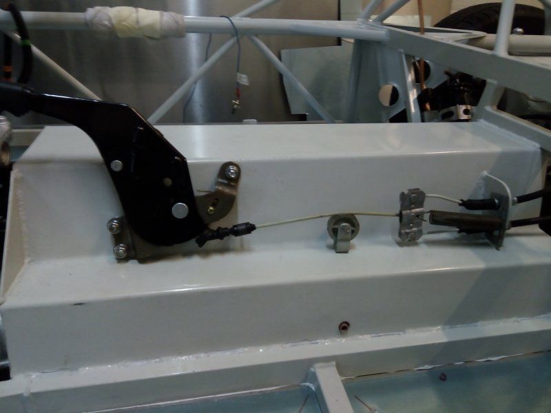
Having taken delivery of new handbrake cables, they could then be installed along with the handbrake lever. In order to establish where the lever needed to be located, the rear cables were firstly connected to their corresponding brake caliper. The free ends were then fed through the guide hole bracket on the side of the transmission tunnel before being connected to the lever and front cable via the compensator. The cables were then held securely in place using spring clips.
Making sure the adjuster nut on the lever was fully backed off (to allow maximum cable adjustment range once fitted) the lever was held against the tunnel so that the cable was taut and the mounting hole positions marked.
These were drilled out and 8mm bolts used to fix the lever securely in position. Note that the front of the lever mounting bracket needed spacers (8mm flange nuts are ideal) fitting between it and the tunnel so that the lever does not interfere with the gear stick. A roller was then installed to hold the front cable and compensator up - preventing it from rubbing on the tunnel.
Brackets were then fabricated to secure the rear cables at their mid-point to the subframe so as to stop them flaying about and possibly fouling on anything. The handbrake and cables were then adjusted as per instructions in the MX-5 owners manual.
FEBRUARY 2018:-
The new set of brake pipe hoses arrived, so these were duly fitted. The time had come to make a start on the wiring and so the donor's loom was draped roughly in position over the chassis so as to determine its layout. All the plugs, connectors and earths were made before temporarily connecting up the battery and each circuit was checked to make sure they all worked correctly.
The Replicar is a relatively simple car electrically - meaning that a lot of the donor car's systems such as power windows, electric mirrors, wipers, central locking, airbags etc. are not required. The redundant wiring could be tied up out of the way, but I wanted to remove it to make the loom simpler and assist in modifying it to fit. So the outer sheathing was removed to expose the individual wires so as to help identify them and to follow their routing within the loom. Once identified with the aid of a multimeter and wiring diagrams, the individual wires were traced and removed one at a time.
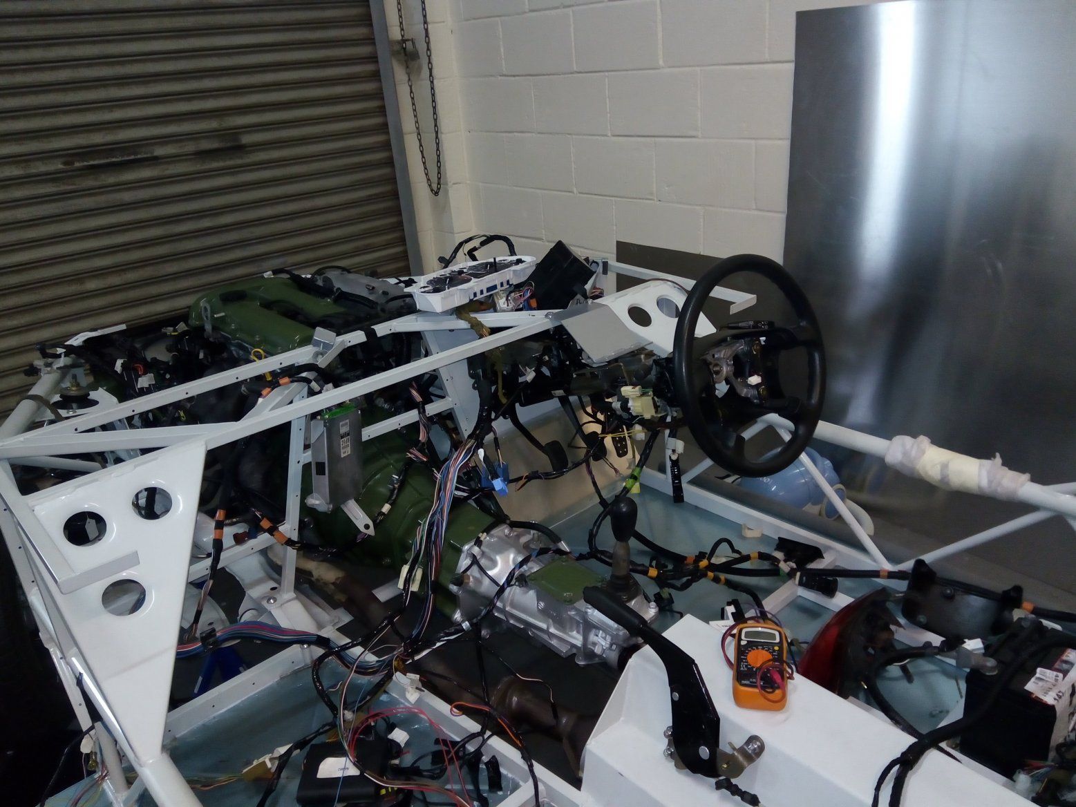
All required remaining circuits were re-checked each time for correct operation before moving on to the next wire to be removed. This is a slow, laborious task but does ensure that if a mistake is made then it's relatively simple to rectify. As each part of the wiring loom is completed, it will be re-wrapped in loom tape and fitted in its final position.
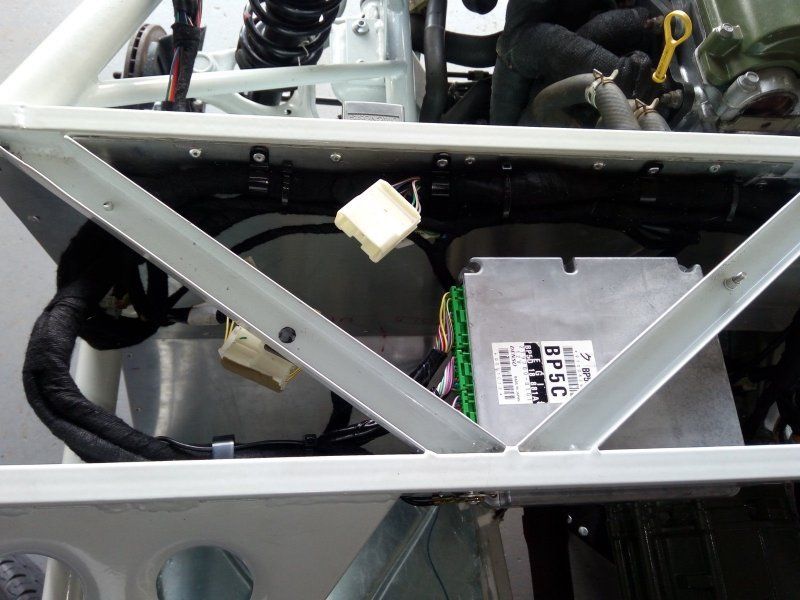
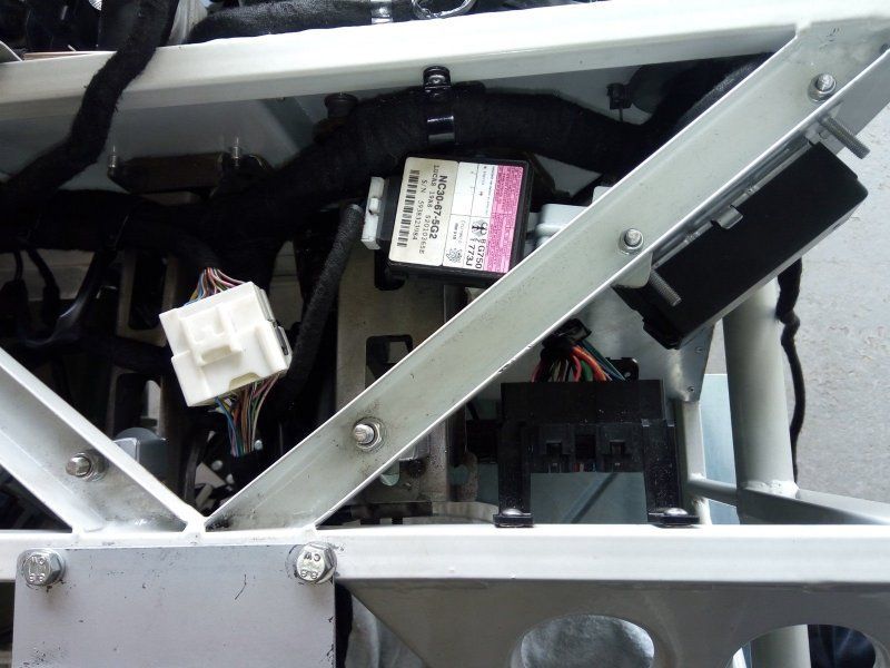
Large holes to accept the original donor's wiring grommets were made in the front bulkhead panels and the panels fixed permanently in place with rivets and PU sealant. The engine bay wiring was pulled through the grommets and the main relay banks/fuse panels etc fixed in position to enable the under-dash wiring to be completed.
MARCH 2018:-
Fabricated and fitted a drip tray to sit under the fuel tank to prevent fuel coming into contact with the hot exhaust in the event of any potential leak. This had to be made in several sections so that it could be manouvered under the corner straps for the fuel tank mounting points.
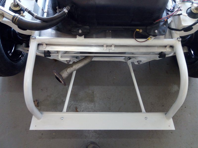
I then moved on to fabricating and fixing in place the panels that make up the rear lower bulkhead. A hole for the battery cable grommet was made and the cables pulled through into the cockpit area behind the passenger seat and fixed firmly in place with p-clips on the rear of the bulkhead. With thoughts moving forward on mounting the body, I decided I wanted to change the method for supporting the rear of the body and embarked on modifying the chassis by extending and curving the tubular side rails downwards.
A plate was then welded across the feet of the tubes so as to act as a sill for the rear bottom lip of the bodywork to sit on. Two tubular struts were then made and bolted to the sill and bottom of the rear subframe to act as a brace between the two. The fuel tank could then be re-instated and fully plumbed/wired in - not forgetting the all-important earth strap.
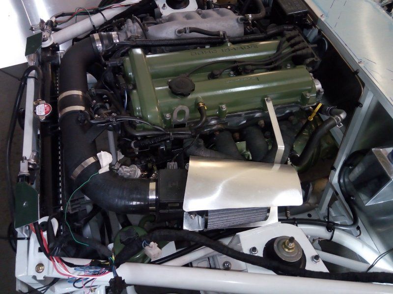
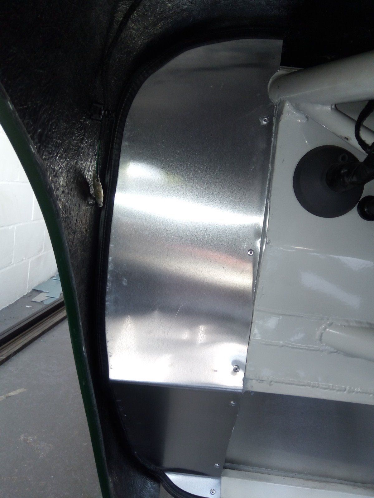
Turning attention to the other end of the car, an after-market air induction system was installed as there isn't enough room in the engine bay for the standard airbox etc. This meant that the cone filter sat adjacent to the exhaust manifold which isn't ideal as it means that warm air would be drawn in by the filter instead of cold dense air. To help counter this a little, I fabricated an aluminium heat shield to protect the filter from a hot exhaust manifold.
Not being particularly enamoured with the original donor expansion tank, I ditched it in favour for a smaller, neater polished aluminium one. This was duly installed on the passengerside bulkhead. The radiator was then slowly filled with coolant and then some added to the expansion tank.
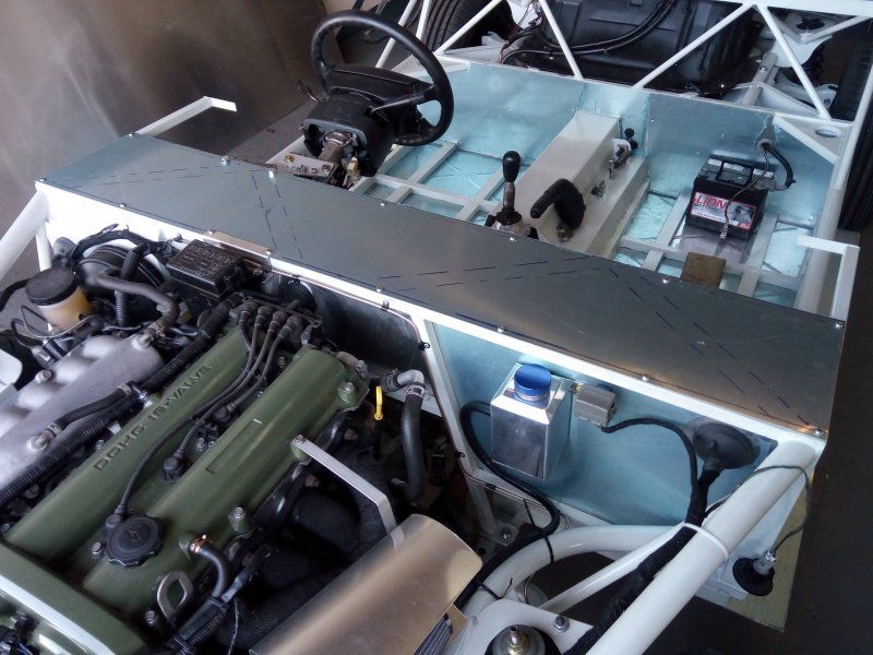
It was time to see if the engine would start. So the battery was temporarilly connected up along with the instrument cluster and, ensuring a fire extinguisher was close to hand, the ignition was turned on and starter motor engaged. Glad to report the engine fired into life almost immediately and was allowed to run for a few minutes to hopefully bleed out any air pockets - all the while keeping a wary eye on the temp and oil pressure gauges. Having the engine start is always a noteable stage in any build.
With most of the mechanical and electrical systems now installed (albeit bar a little final tidying etc), it was time to consider the body fitment. In order to aid alignment, I fitted the new larger diameter 15" wheels and tyres which had arrived. These will fill the arches better and hence aid their centralisation within them. The body was then placed over the chassis and manouvered into position so that measurements could be taken to manufacture appropriate brackets and rubber mounts to permanently fix it in place when it's finally fitted.
APRIL 2018:-
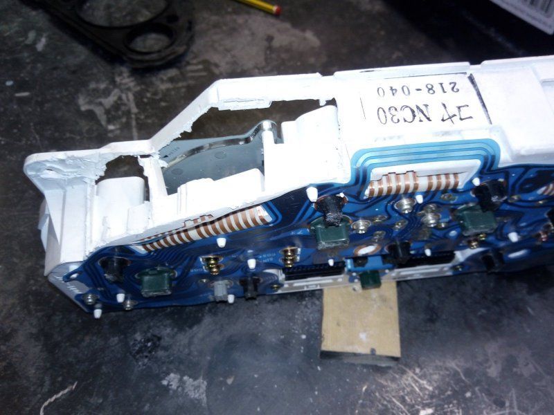
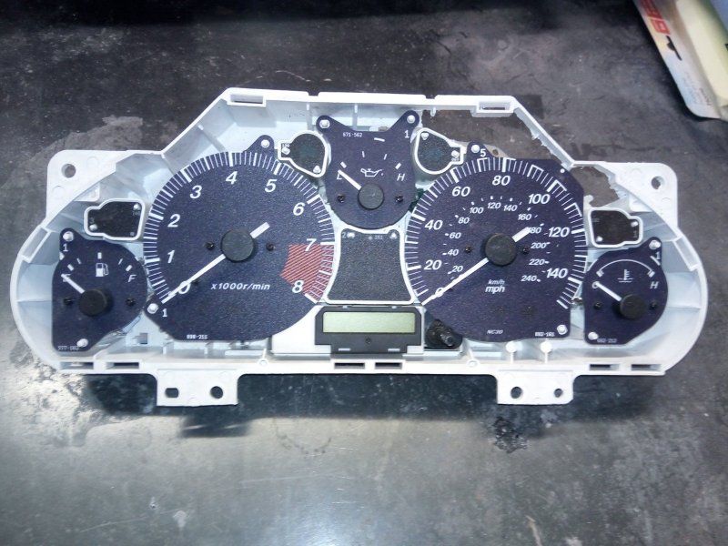
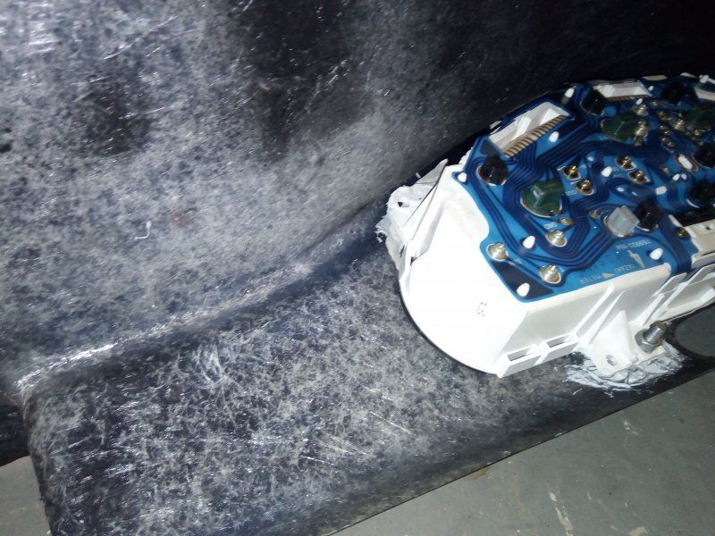
The dash panel was built using the donor's original instrument cluster. I wanted to end up with a period look to the instruments and so purchased a set of trim rings so that when finally fitted, the dials would look like individual instruments.
It was time to set about dismantling the cluster: The clear perspex cover was removed and the black fascia underneath also taken off the front of the cluster to reveal the dials underneath. The hooded cowl and mounting clips were removed from the fascia so as to form a flat template and to enable it to eventually lie flat behind the dash panel itself. The casing of the cluster had to have material removed from the upper corners (being careful not to damage the flexible PCB in the process) so as to enable it to sit as high as possible within the dash's hump.
Once its final position had been established, a 5mm hole was drilled in the dash panel to locate the trip meter reset spindle. The front of the dash was then masked off and the black fascia laid on top so that its spindle hole aligned with that made in the dash with said 5mm drill bit. It was then used as a template to mark the outlines of the seperate instruments and warning lights etc. on the masking tape.
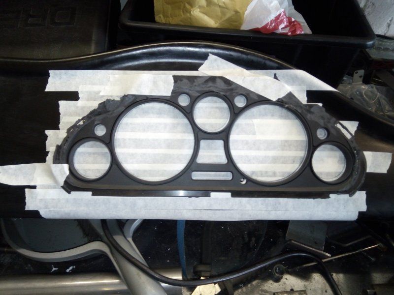
A 90mm hole saw was used to drill out the initial holes for the rev counter and speedo and a 42mm saw used for the smaller dials. The holes were then gradually opened up with a half-round file until the polished aluminium rings were a press fit in them.
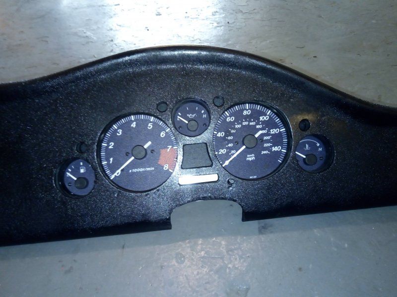
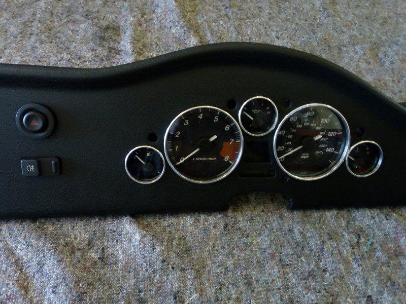
The rings were removed and the dash panel sent off to be covered in a textured leather effect vinyl wrap. The result is very convincing. Big Head fasteners were secured to the back of the dash with a 2-pack resin called VUDU GLU which is very strong once set.
A thin piece of clear perspex sheet was fixed to the back of the dash over the instrument holes with the same resin and allowed to set before spacers were slipped over the Big Head studs. These make the cluster stand off the back of the dash when it then mounted on the studs - to give clearance between the raised bosses of the instrument needles and the clear perspex. The polished rings were once again pressed into place for the finishing touch.
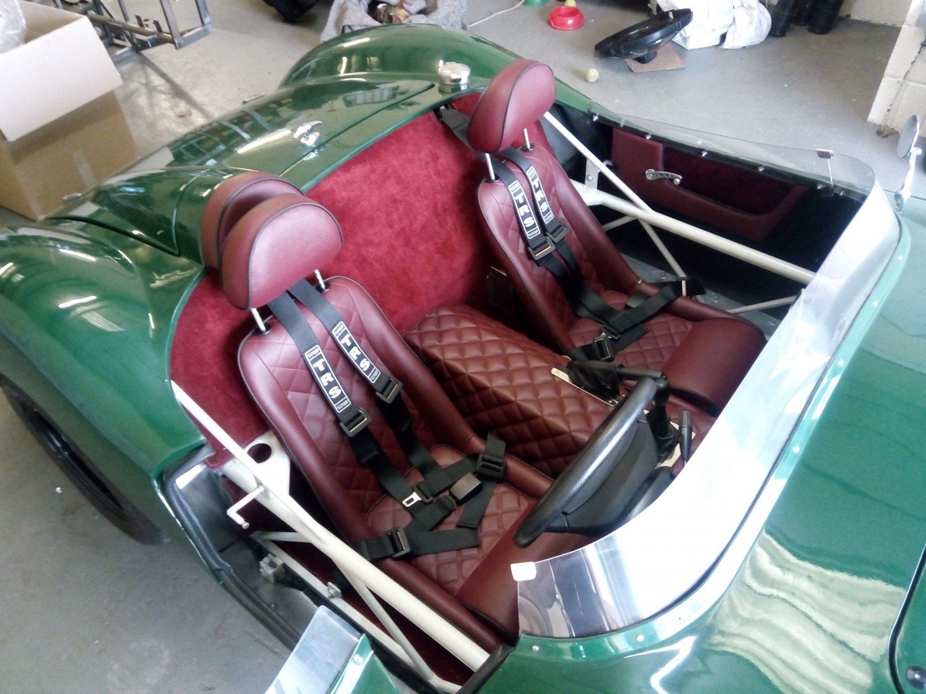
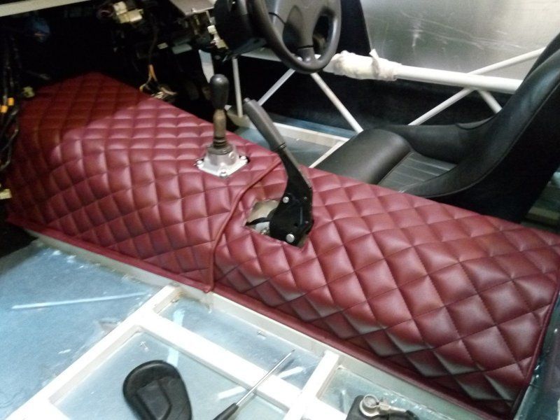
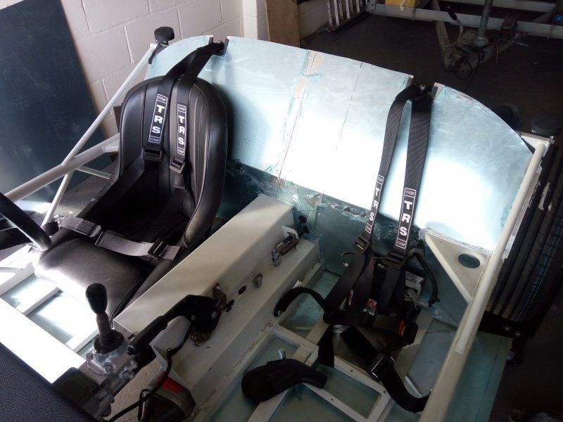
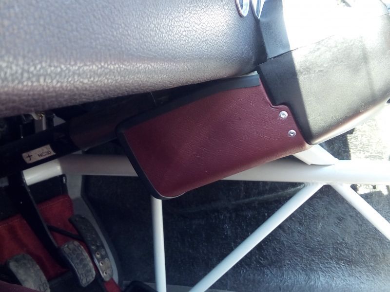
Other jobs completed were the manufacture and fitting of the upper rear bulkhead panels along with the installing of the harnesses. Having decided on a dark red and black interior to complement the British Racing Green bodywork, the transmission tunnel sections were sent off to the trimmers to be covered in a diamond stitched Jaguar Mulberry Red vinyl.
MAY 2018:-
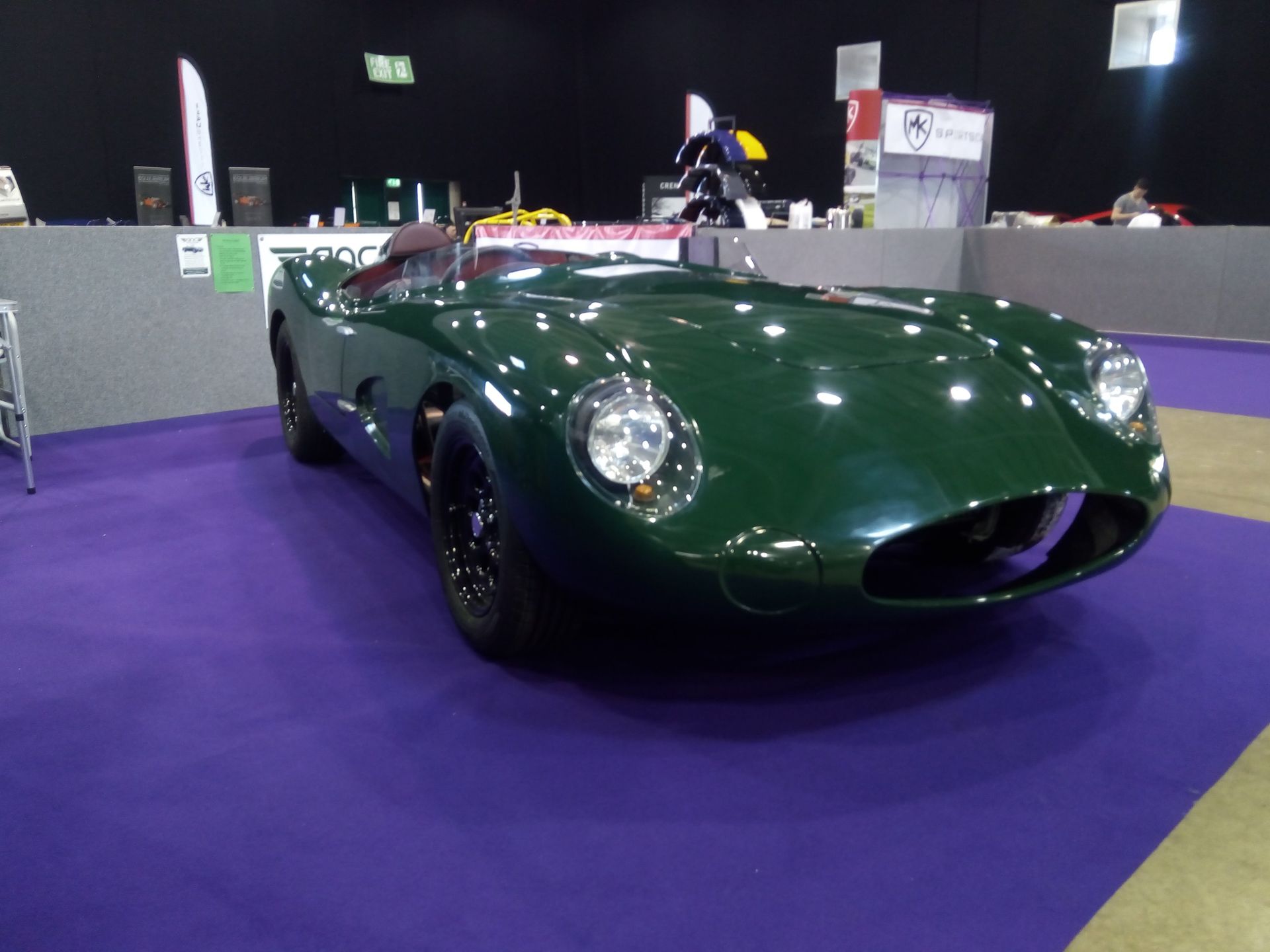
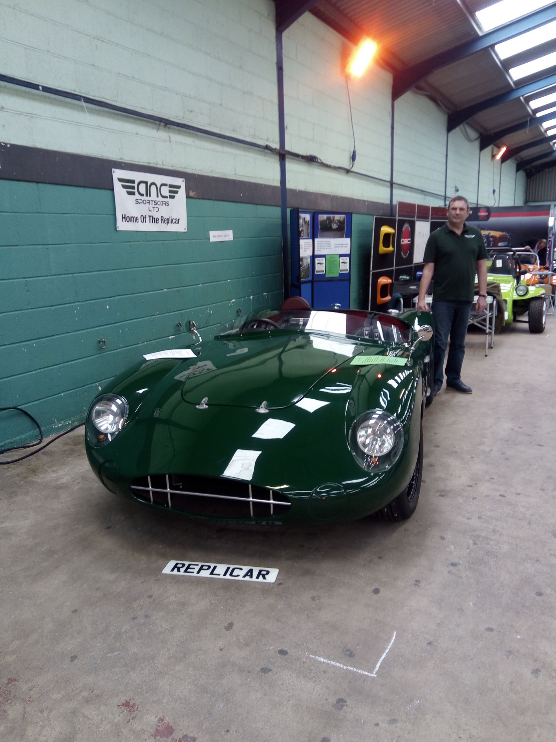
The latter part of April and first week of May was spent readying the car for the Stoneleigh National Kit car show. Although not finished, the build was advanced enough to be able to get it to a presentable condition to exhibit.
This meant permanently fitting the body and dash to the chassis, fitting the headlamp cowls, flyscreen and then carpeting the rear bulkhead and floor.
There was a lot of hard work involved in showing at Stoneleigh - what with the travelling, setting up the stand and camp base etc. Although tiring, both my wife and I thoroughly enjoyed the weekend - especially talking to potential customers and existing builders alike.
Still, all the effort was worth it as we came away with several confirmed orders - so all in all, our first show can be considered a great success. We learnt a lot and no doubt will implement new ideas for next year's show. The remainder of May was spent dealing with the orders from the show - so working on the car had to take a back seat.
JUNE 2018:-
Managed to get a few small jobs done on the demonstrator in between working on orders. Firstly, I fabricated and fitted a profiled aluminium panel to fill in the gap between the top of the bulkhead and the scuttle to help seal off the engine bay from the cockpit.
To further seal off the cockpit from the open wheelarches, four infill panels were made from aluminium sheet. A small profile boot type rubber seal was fitted to the edges so as to fill in any gaps between the panels and bodywork once fixed in place in each corner.
Thoughts were then turned to the doors and what latching method to use. I decided to emulate what I had seen on the Road Runner Racing Replicar - which is simple but strong. A pair of mini bear claw catches with the required double latching needed for IVA were purchased - and one fitted to each door.
A pair of strikers were made out of 12mm dia. round tube which had the striker bolts welded in one end and a M10 x 1.5 thread tapped into the other to accept a threaded stud.
The chassis had to be modified to create a mounting point for the striker and so a 40mm x 3mm strap was welded into the chassis. Ensuring the striker and door catch were aligned, a 10mm hole was then drilled in the strap at the appropriate point. The striker and bracket were painted to match the chassis' powder coat before the striker was secured to it with a plain nut on one side and a nyloc on the back.
A little bit of final adjustment and the door closes with a good positive satisfactory clunk. Rather than a strap, customer's chassis' now have a full triangular gusset welded in place so as to allow for any variation in door alignment between individual builds when locating the striker mounting hole.
JULY 2018:-
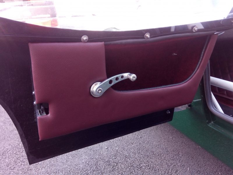
With the door catches done, it was time to consider a method of operating them. I was going to use a pull cord hidden in the door pocket but under closer scrutiny I decided it would not be as neat a solution as I would've liked. Trawling through various sites etc for an alternative, I came across and purchased a cheap pair of window winders on ebay which I thought could be modified to act as door release levers.
Once arrived, I set about doing just that. A pair of spindles were made from 10mm round bar and welded on to the bell crank levers from the original donor's door locking mechanisms. Further parts from the donor locks were removed and modified such as the operating rods which were cut down to a suitable length and re-profiled before being connected between the door catches and release levers - again using the original clips from the donor.
A hole was drilled in the inner door pocket panel to accept the lever's spindle and the lever mechanism fitted to the door. Finally, a spring was added to ensure the lever would return under tension when used.
AUGUST 2018:-
The rear exhaust section needed some thought with regards to options for suitable silencers that would fit within the boot area. Wanting to avoid the cost of a bespoke system, I looked at various silencers for production cars and settled on the back box for a Mk1 Ford Focus. It would still need adapting, however, to fit.
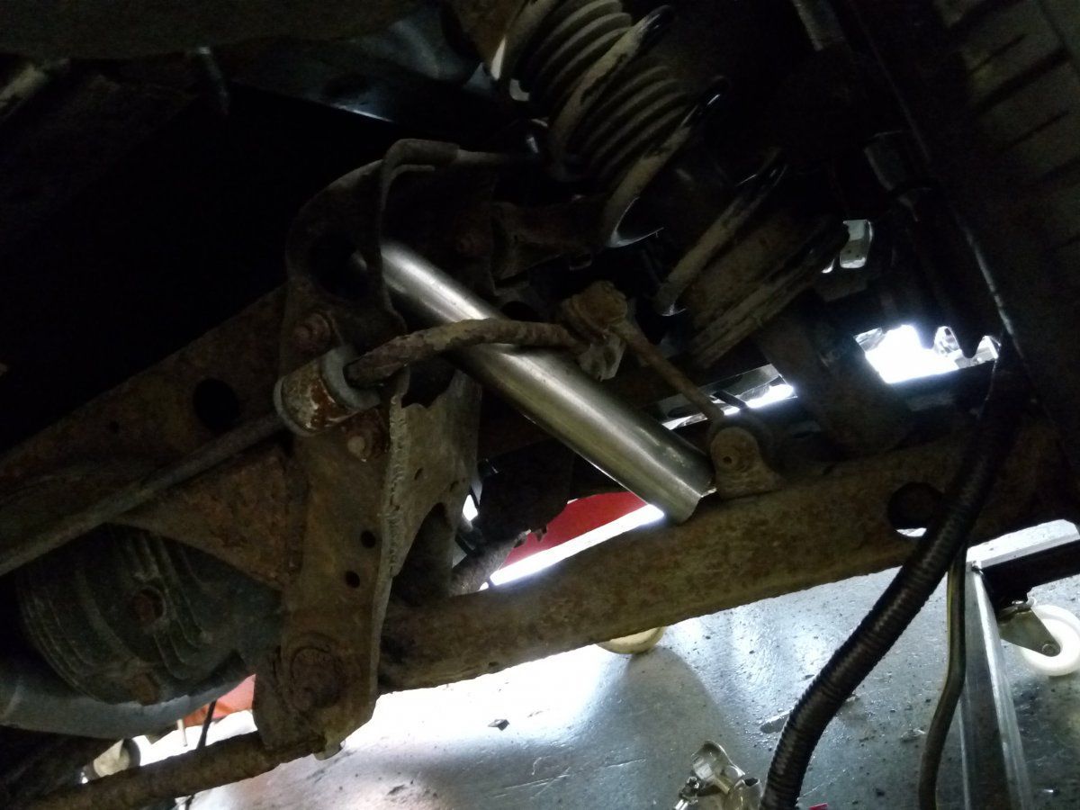
Thus, the inlet bend and flange (A) along with the mounting bracket were removed from the original Mx-5's rear silencer and welded on to the inlet side of the Focus silencer. Old sections of 2" exhaust pipe with suitable bends were cut and welded together to form a suitable tail pipe (C) which would exit and clear the rear of the car. Again, this was then welded on to the oulet side of the focus silencer. A further mounting bracket (B) was fabricated and welded on to the tail pipe before the whole silencer assembly was given a coat of heat-resistant paint.
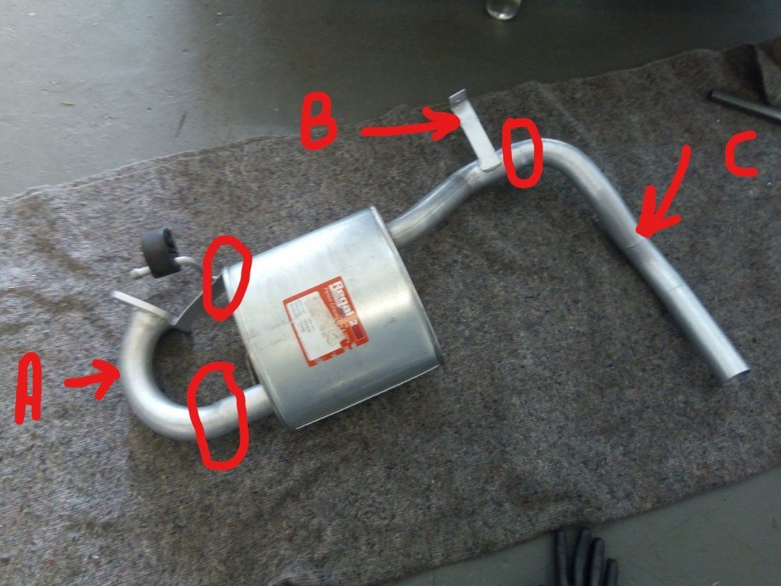
Once dry, the new silencer was attached to the existing centre section using the flange and mounted on to the car subframe using a suitable exhaust bobbin and rubber coupling. A suitably radiused polished trim was finally added for the finishing touch.
SEPTEMBER 2018:-
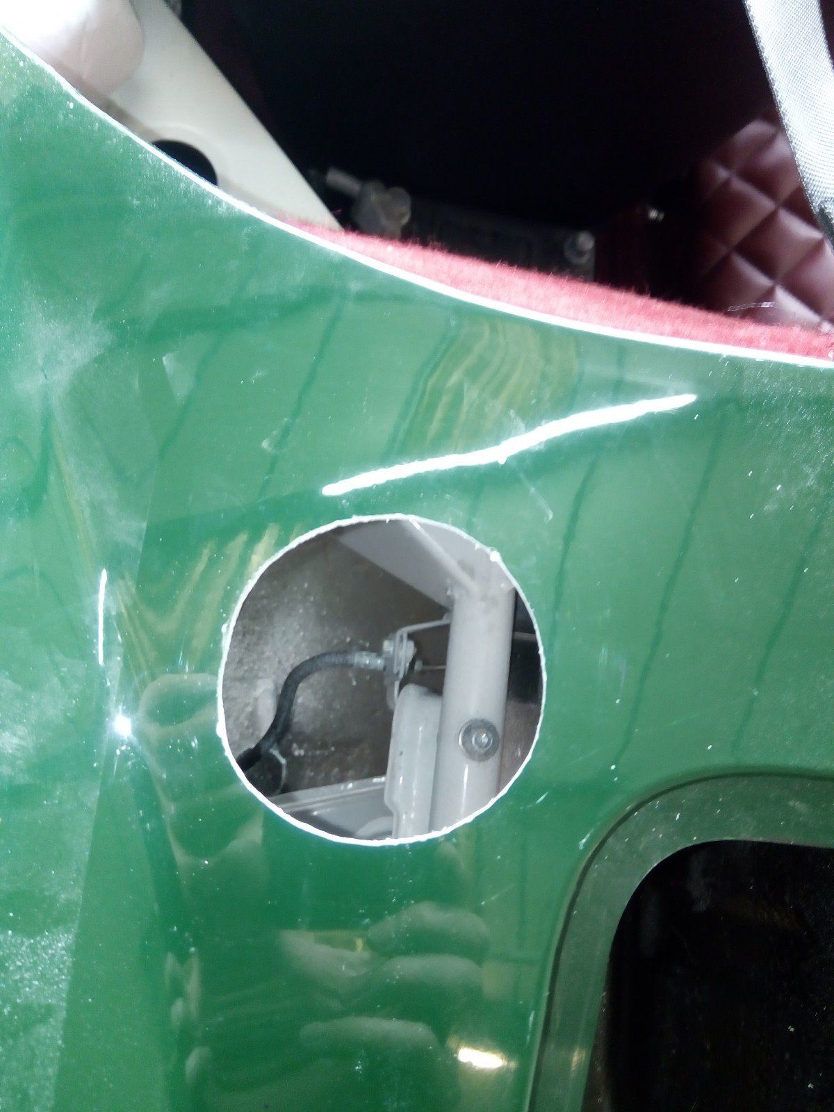
Having sourced a suitable classic Aston-style petrol filler cap, it was time to install it and connect it to the fuel tank. I used the same chain-drilling method used previously in the build for cutting out the headlamp holes, to form a suitable diameter hole to mount the cap in the top of the n/s rear wing. The original donor's filler tube was shortened and modified so that it could be used as a reducer between the cap's larger diameter filler neck and that of the fuel tank inlet. It also retained its 'breather tube' to aid speed when filling up.
A bracket was made and welded to the filler tube to both support it and secure it to the chassis. Finally, it was all connected together using the correct grade flexible tubing for unleaded fuel (proof of this will have to be presented at the IVA test).
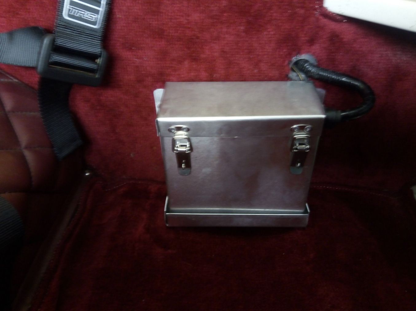
Having mounted the donor's battery in the cockpit behind the passenger seat, it became apparent that although it is relatively small, it would prevent the seat from going fully back. After some research, I decided upon fitting a much smaller race battery which was still able to supply enough cold cranking current to turn the engine over easily.
To protect it from the elements, I fabricated a box to house it from aluminium sheet which was then secured firnly to the rear bulkhead. The underside of the lid was insulated with rubber and the battery terminals also fitted with suitable shrouds so as to remove any possibility of them shorting out on the lid!
OCTOBER 2018:-
Attention was turned to the boot and bonnet and how to secure them. Using IVA-friendly 'Cobra' style external hinges, the boot lid was attached to the bottom of the boot apperture. A suitable 'T' handle/catch assembly was fitted to the upper edge of the lid so that the catch would engage with the underside of the boot flange when closed and locked. Lastly, a small profile boot seal was fitted to the flange of the boot's apperture.
The bonnet needed more consideration on how I was going to mount it. The simple option would have been to bolt it down at each corner - but I wanted to hinge it so as to prevent it possibly getting damaged when being taken off/on the car and look a little more aesthetically pleasing.
However, looking around for sutiable external hinges proved largely friutless until I hit upon using classic Mini boot hinges as they are relatively small. These were straightforward to fit. However, I may look into developing an internal hinge system in the future as they do tend to spoil the lines of the car a little. I had also come across push-button bonnet pins to hold the bonnet closed. They are low profile and hence relatively inobtrusive. It will remain to be seen if they hold out under driving conditions (I can always add leather bonnet straps if need be!)
To tidy up the interior, a pair of door cards were made out of thin ply and covered in a thin layer of foam before being finished in the same colour vinyl as the transmission tunnel etc.
Also, an additional shroud was made out of aluminium sheet before again being covered in the same vinyl. This was then fixed to the lower steering column cowling so as to give additional protection and cover any sharp edges on the electrical connectors of the column wiring etc.
NOVEMBER 2018:-
The bespoke wheel spacers arrived from Freaky Parts. These were designed to be dual purpose in that the main boss will act as a spigot to centralise the pepperpot wheels on the hubs. The wheels have a centre bore of 67.1mm and the MX-5 hubs are 54.1mm, with the spigot taking up the clearance between the two. The boss will also hide the otherwise exposed ugly hub nuts.
Early November saw us at the Bristol Classic & Restoration Show. There was a hall dedicated to kit cars which had several manufacturers and clubs displaying their cars. The replicar was met with favourable comments and a few enquiries which will hopefully result in sales in the near future.
Hopefully, the kit car side of the show will grow over the coming years and become a viable South West alternative to the Exeter kit car show which sadly ceased several years ago.
JANUARY 2019:-
The seats arrived from Intatrim and very nice they look too! These are their Nova seat and have a more raked backrest than others. This means that I sit lower in the car and further back giving a little more legroom and reach. They did a cracking job of matching the colour and quilting of the existing interior.